Backplane & card cage construction
In the fall of 2002 I'd been working seriously on this project for a year and
half, without anything physical to show for it. All of the work was design
and simulation. I was a bit tired of that, and decided to go ahead and
build a backplane - even though I wasn't anywhere near being able to begin the
real construction.
The pictures below show the process, and at the time I was pretty pleased
with how it came together. However, since then I've realized that my power
and ground distribution is wholly inadequate. I've thought a bit about how
to fix this, and I think the route I need to go is to have some custom PCBs
made. However, to do it right I would need a 5 layer board - which would
cost a bit more than I'd like to spend. One fix possibility is to do a
two-layer board that just does power & ground. I could then just sandwitch
it on top of my existing backplace. The big problem with that is it would
close things off. If there was a single wiring mistake, I would be unable
to correct it, and would have to trash the whole thing. Another option is
to trash what I've done, get the two-layer board and use it as a base.
Then, I'd redo all of my wire-wrapping to connect the signals together.
As of now (1/3/2004), my inclination is to go with the sandwitched two-layer
appoach - but I'll put off that decision for awhile.
Anyway, here are the photos. Click on a picture to get the hi-res
version.
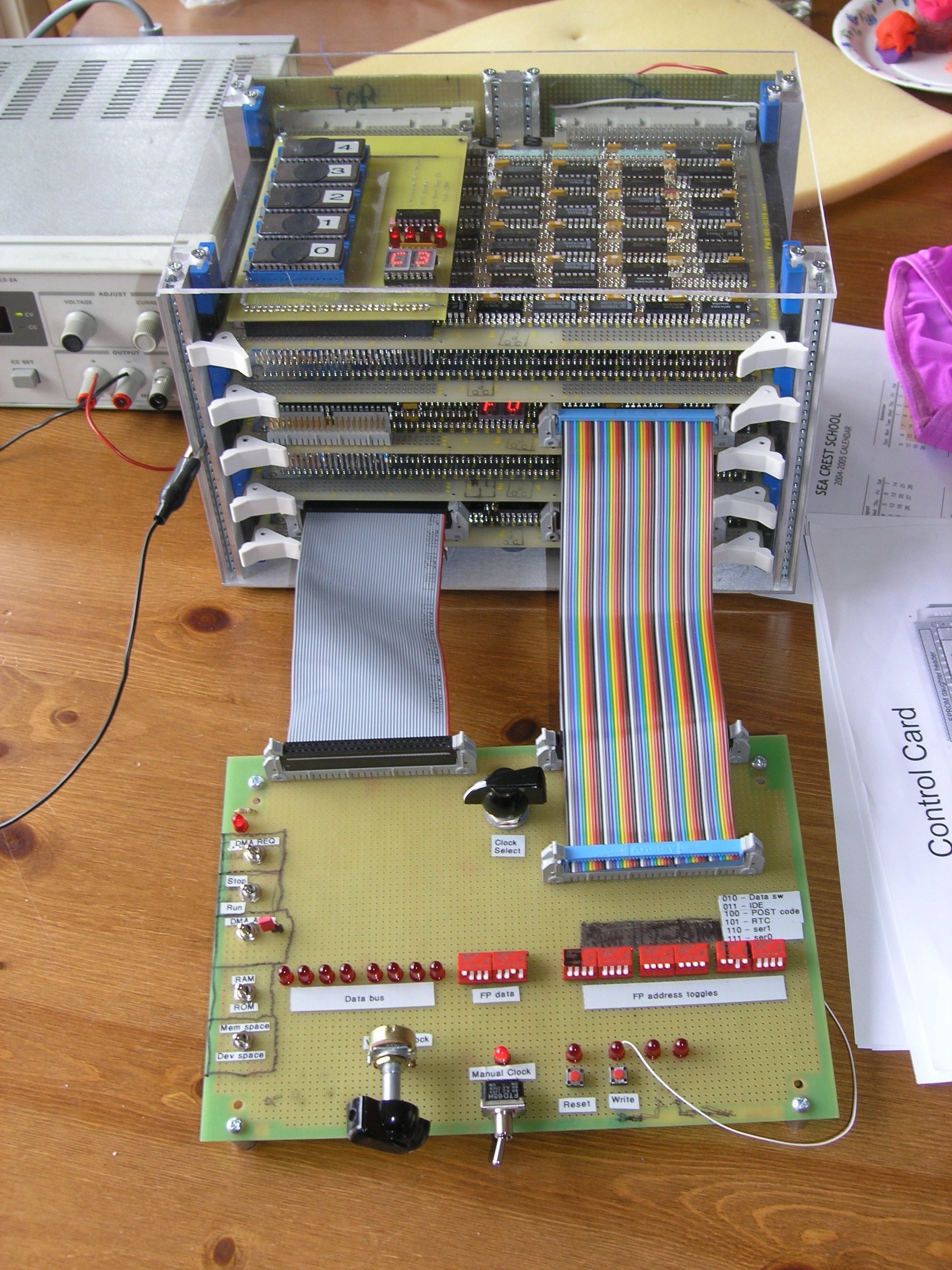
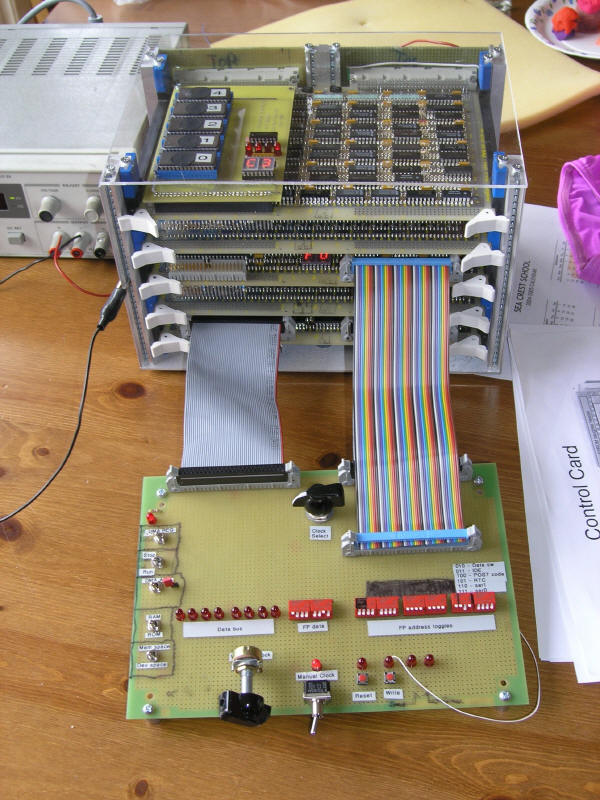
3/20/2004
Took the cover off of the card cage to let me see the LED display on the
EPROM daughter board, and after a while the posts were getting a little wobbly.
So, I cut a piece of plexiglas and installed it to make the cage more sturdy.
Here's a picture:
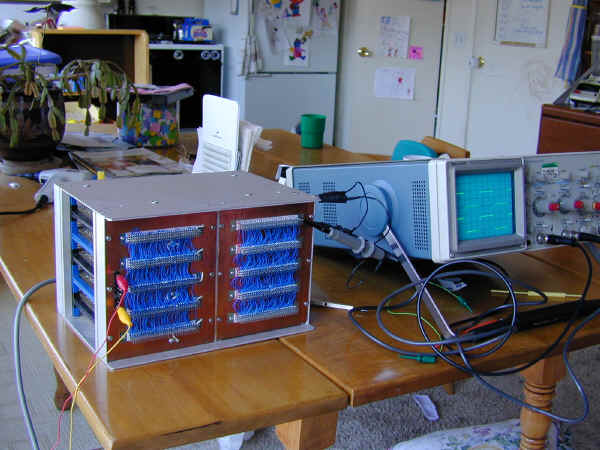
9/22/2002
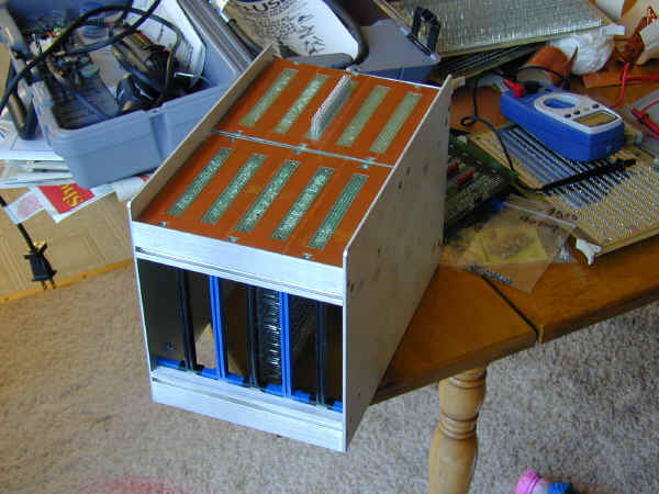
The backplane is complete, and I've been playing around with how the signals
look.
9/19/2002
I've completed the left half of the backplane. Lots of wires done, lots
of wires to go....
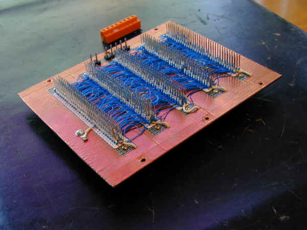
I'm
running power and ground into the left half. The right half will pick up
ground through the chassis (as well as some dedicated traces).

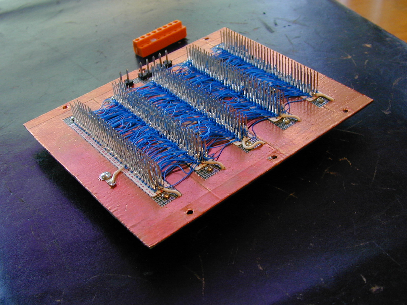
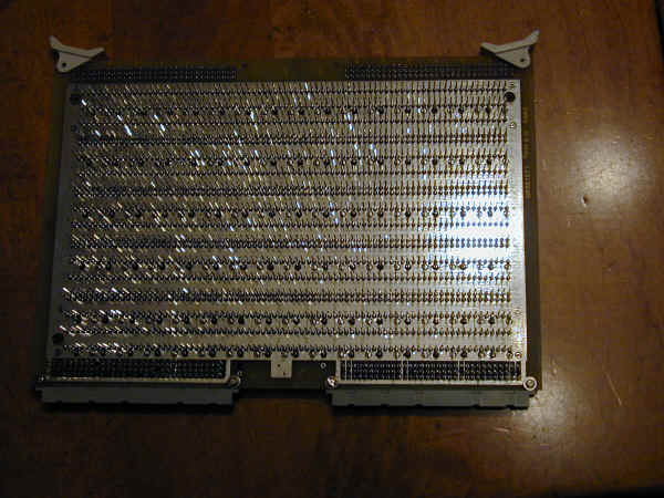
Here's
the back side. A bit of overkill, but that will be a theme throughout
construction.
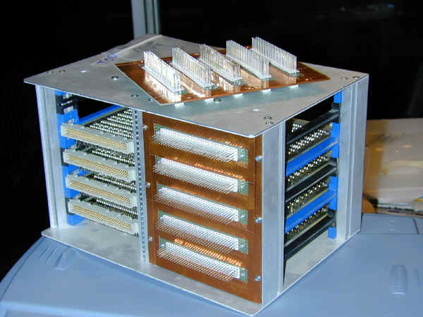
9/8/2002
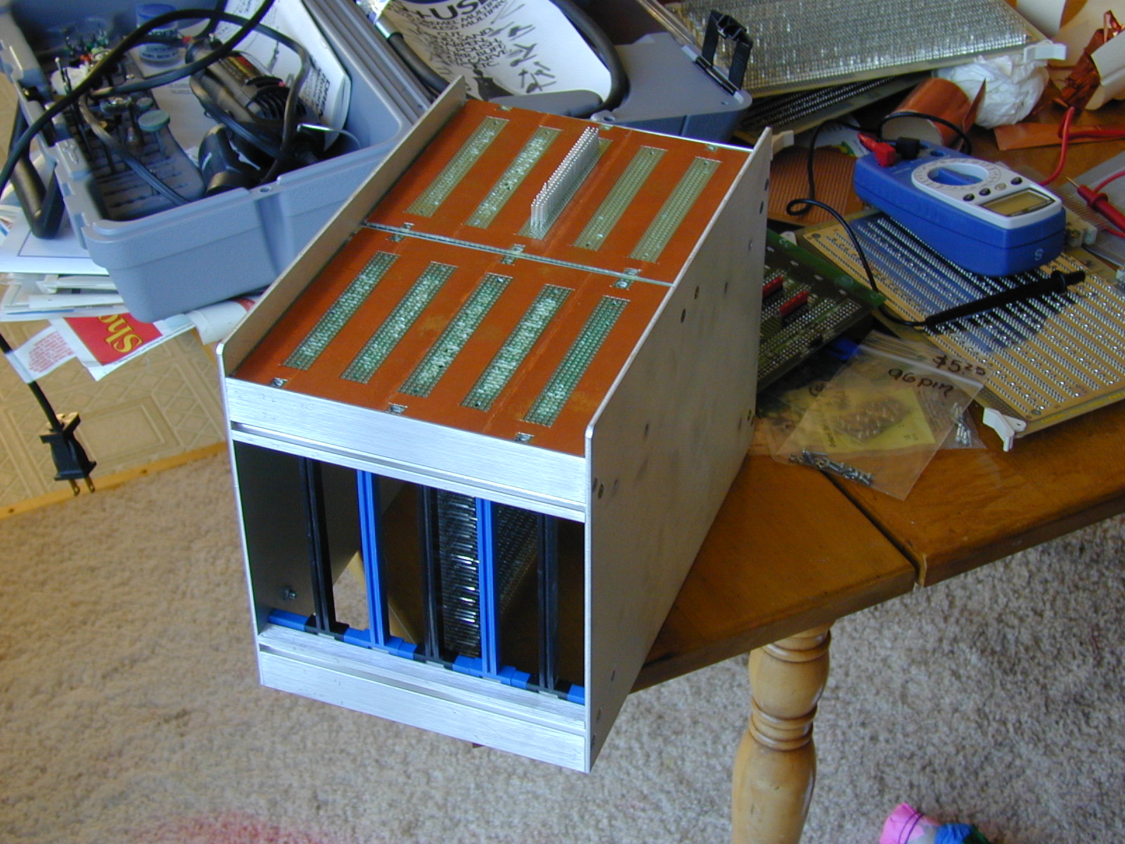
The first real construction began this weekend. I bought a nice card
cage on eBay which will fit 5 of my wire-wrap prototype boards. The cage
was set up to take 7 boards, but I spaced it out to allow for the wire-wrap
pins. To create a backplane, I'll be wire-wrapping along the spine. I'm backing the backplace with a copper-clad
perfboard to reduce noise.
The
screws were an odd size - 2.5mm, but I found some at HSG in Santa Clara.
The white strips are wire-wrap tags. I'll be using them throughout.
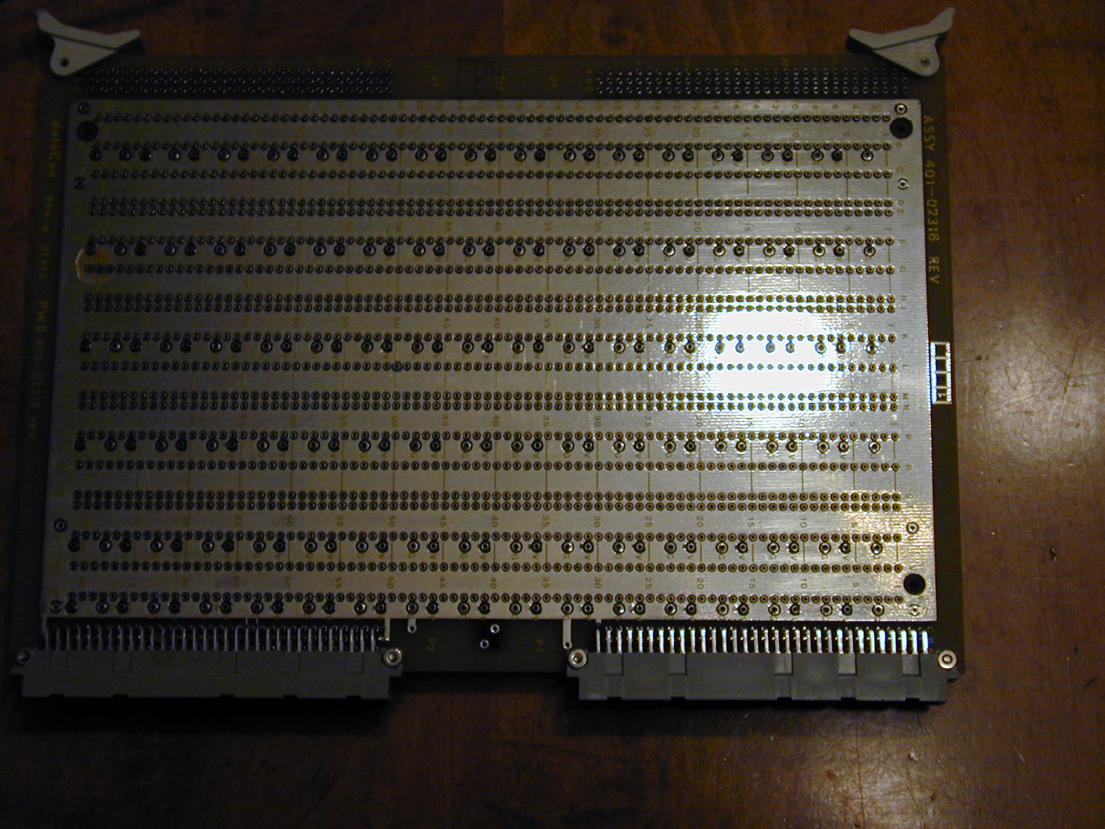
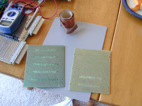
Pin side of the wire-wrap cards. I got them from Excess Solutions in
San Jose, at $15 each.

The component side.
I had to do a little sanding to get things to fit, but it looks pretty
good. Next step is to find some more machine screws of the right side, and
I also need to decide what kind of socket arrangement I'll use to connect to the
power supply. After that's done, the wire-wrapping begins.

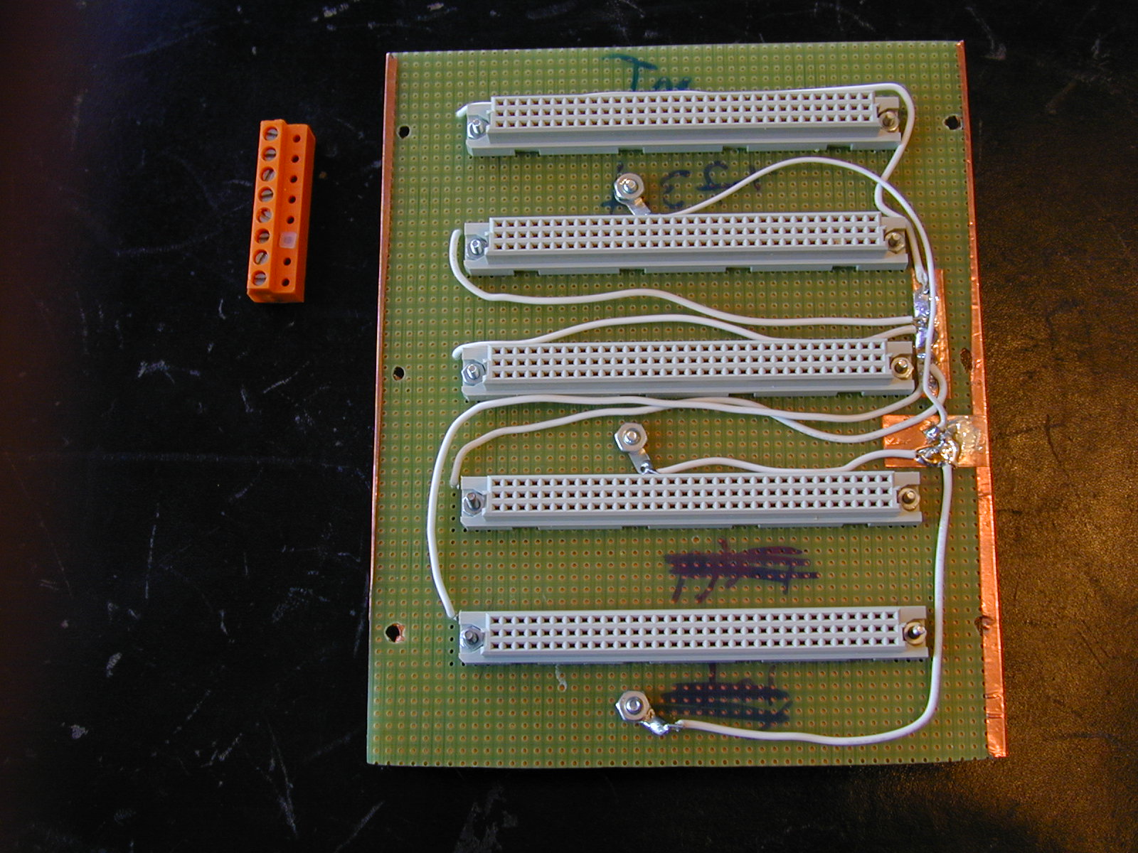
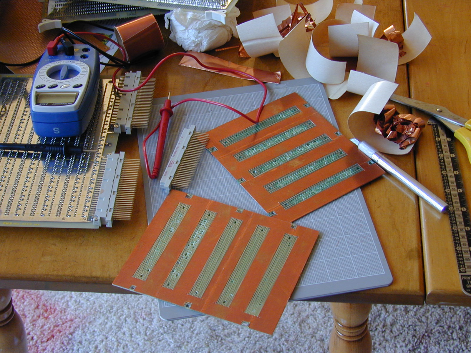
Here they are after covering them with copper tape, and the
cutting out holes for the mounting screws and wire-wrap sockets.
I didn't have perf-board big enough, but had some pad-per-hole prototype
boards on hand. It's a waste, but I cut two of them
down to fit the backplane opening. Unfortunately, 96-pin wire-wrap sockets
had wide portions of the pins at the bottom, presumably to give them a tight
fit. To make them work with my boards, I had to use a Dremel tool to widen
the holes. It was a bit messy doing it free-hand, but it worked.
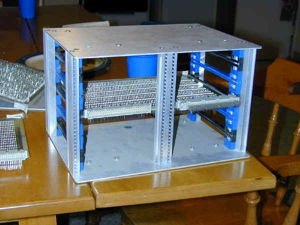
The cage after re-spacing the guides.